Remote Control Car PCB Circuit Everything You Need to Know
A remote control car PCB circuit is the brain and nervous system of your RC vehicle, controlling every function from steering to speed. This guide covers the essential components, design process, and troubleshooting tips you need to understand RC car electronics. Whether you are a hobbyist building a custom setup or a curious tinkerer, you will find practical insights to level up your remote control car game.
If you have ever wondered what makes a remote control car move, steer, and respond to your commands, the answer starts with a small but powerful piece of technology. The remote control car PCB circuit is the electronic heart of every RC vehicle you have ever played with. It is the green board filled with tiny pathways, chips, and components that bring your car to life.
Whether you are a seasoned hobbyist or just starting out, understanding how this circuit works opens up a whole new world of possibilities. You can troubleshoot problems faster, build custom setups, and even design your own boards from scratch. This guide breaks down everything you need to know about RC car circuit boards in simple, easy-to-follow terms.
We will walk through the main components, how they work together, common issues, and practical tips to keep your remote control car electronics running at their best. By the end, you will have a solid grasp of RC car PCB design and why it matters so much for performance.
Key Takeaways
- Core Function: The PCB circuit manages power distribution, signal processing, and motor control in your RC car.
- Key Components: Transmitter, receiver module, ESC, servo motor driver, and microcontroller are the essential parts.
- Design Matters: Proper PCB design affects signal quality, heat dissipation, and overall performance of your RC car electronics.
- Maintenance is Simple: Regular cleaning, inspection, and soldering checks keep your circuit board running smoothly.
- Common Issues are Fixable: Most problems like signal interference or motor stuttering can be resolved with basic troubleshooting.
- Custom Builds are Rewarding: Building your own PCB gives you full control over performance and customization.
📑 Table of Contents
- What Is a Remote Control Car PCB Circuit?
- Key Components of an RC Car PCB Circuit
- How RC Car PCB Circuits Work
- Designing Your Own RC Car PCB
- Common Problems with RC Car PCB Circuits
- Tips for Maintaining Your RC Car PCB Circuit
- Expert Insights on RC Car PCB Electronics
- Key Takeaways
- Frequently Asked Questions
- Conclusion
What Is a Remote Control Car PCB Circuit?
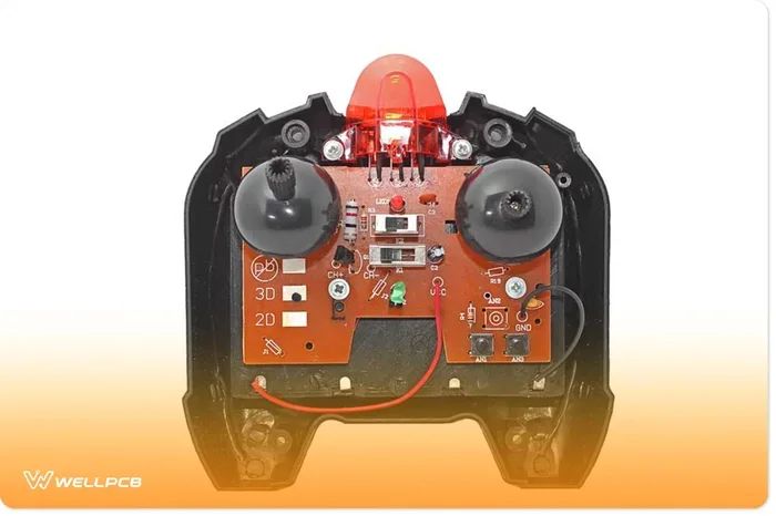
A printed circuit board, or PCB, is the flat board that holds and connects all the electronic parts inside your RC car. Think of it as a highway system for electricity. Instead of loose wires tangled everywhere, the PCB uses copper traces to guide signals and power to the right places at the right time.
The remote control car PCB circuit controls several critical functions. It receives signals from your transmitter, processes them, and sends commands to the motors and servos. Without this circuit board, your RC car would just be a pile of plastic, metal, and motors with no way to respond to your remote.
Why PCB Circuits Matter for RC Cars
RC car electronics have come a long way. Older models used simple point-to-point wiring. Today, hobby-grade RC car electronics rely on compact PCB designs that fit more functionality into a smaller space. This means faster response times, better signal clarity, and more reliable performance on the track or in your backyard.
A well-designed circuit board also reduces the risk of short circuits and signal loss. When every trace is properly routed and every component is securely placed, the entire system runs smoother. That is why PCB design is such a big deal in the RC world.
Key Components of an RC Car PCB Circuit
Every remote control car PCB circuit has a set of core components that work together. Let us break them down one by one so you know exactly what is happening on that little green board.
Transmitter and Receiver Module
The transmitter is the remote control you hold in your hand. It sends radio frequency signals to the receiver inside your car. The receiver module picks up these signals and passes them to the PCB circuit for processing.
Most modern RC cars use 2.4 GHz radio frequency control. This frequency band offers a long range and very little interference from other devices. The transmitter circuit in your remote encodes your stick movements into radio signals, and the receiver decodes them back into actionable commands.
Electronic Speed Controller (ESC)
The ESC is one of the most important parts of your RC car PCB circuit. It controls the speed of your motor by regulating the power supply. When you push the throttle on your transmitter, the ESC interprets that signal and adjusts the current going to the motor accordingly.
There are two main types you will encounter. Brushed motor controllers work with traditional brushed motors. They are simpler and more affordable. Brushless ESC units are more advanced, offering better efficiency, higher speeds, and longer lifespan. If you are building or upgrading a hobby-grade RC car, a brushless ESC is the way to go.
Servo Motor Driver
The servo motor driver handles steering. It receives signals from the receiver and converts them into precise physical movements of the steering mechanism. A good servo driver ensures smooth, responsive turns without any lag or jitter.
Servo quality varies a lot. Cheap servos can feel sluggish and wear out quickly. Upgrading to a metal-gear servo with a better driver circuit makes a noticeable difference in how your car handles. It is one of the easiest upgrades you can make to improve your RC car electronics.
Microcontroller and Signal Processing Board
Many advanced RC car PCB circuits include a microcontroller. This tiny chip acts as the brain, processing multiple inputs and coordinating outputs. It can handle complex functions like ABS braking, gyro stabilization, and programmable light effects.
The signal processing board works alongside the microcontroller to clean up incoming signals. It filters out noise and interference, ensuring that your commands reach the motors and servos accurately. This is especially important in crowded environments where multiple RC cars are running at the same time.
Battery Management Circuit
Power management is critical for any RC vehicle. The battery management circuit monitors voltage levels, prevents overcharging, and protects against short circuits. It ensures that your car PCB assembly receives a steady, safe supply of power throughout your driving session.
Lithium polymer batteries are the most common choice for RC cars. They deliver high energy in a compact size, but they need proper management. A good battery management circuit on your PCB helps extend battery life and keeps your RC car safe to use.
How RC Car PCB Circuits Work
Now that you know the key parts, let us look at how they all work together. Understanding the flow of signals and power gives you a much clearer picture of how your remote control car actually operates.
Signal Flow From Remote to Car
Here is the step-by-step process of how your commands travel through the RC car circuit board:
- You move the joystick or trigger on your transmitter.
- The transmitter circuit encodes that movement into a radio signal.
- The signal travels through the air to the receiver module in your car.
- The receiver passes the decoded signal to the PCB circuit.
- The microcontroller and signal processing board interpret the command.
- The ESC receives the speed command and adjusts motor power.
- The servo motor driver receives the steering command and moves the wheels.
All of this happens in milliseconds. The entire process feels instant because modern RC car electronics are designed for speed and precision. The PCB trace routing on your board plays a big role in how fast and clean these signals travel.
Power Distribution on the Board
Power starts at the battery connector and spreads across the PCB through dedicated traces. Each component gets the exact voltage it needs. The power distribution network on a well-designed PCB ensures that the ESC, microcontroller, and servo driver all receive stable power without voltage drops.
Poor power distribution can cause all kinds of problems. You might notice your car stuttering, your steering feeling weak, or the receiver cutting out randomly. These issues often trace back to how power is routed on the circuit board.
Designing Your Own RC Car PCB
If you are feeling adventurous, designing your own remote control car PCB circuit can be an incredibly rewarding project. It lets you customize every aspect of your RC car electronics to match your exact needs and preferences.
Choosing the Right PCB Substrate Material
The substrate is the base material of your PCB. FR-4 fiberglass is the most common choice for RC car applications. It is durable, heat resistant, and affordable. For high-performance builds, you might consider aluminum-backed PCBs that offer better heat dissipation.
Your choice of PCB substrate material affects how well your board handles heat and stress. RC cars vibrate a lot, and they can get hot during extended use. Picking the right material ensures your car PCB assembly lasts a long time.
PCB Trace Routing Best Practices
Trace routing is the art of laying out the copper pathways on your board. Good routing minimizes signal interference and keeps power delivery stable. Here are some tips to keep in mind:
- Keep signal traces short and direct to reduce resistance.
- Separate power traces from signal traces to avoid interference.
- Use wider traces for high-current paths like those leading to the ESC.
- Add ground planes to reduce noise and improve signal quality.
- Leave enough space between traces to prevent short circuits during manufacturing.
Proper PCB trace routing is what separates a mediocre board from a great one. If you are designing a custom PCB for your RC car, spend extra time on this step. It makes a real difference in performance.
Tools You Need for a Custom PCB Build
You do not need a professional lab to build your own RC car PCB. Here is a simple list of tools to get started:
- A PCB design software like KiCad or EasyEDA.
- A PCB etching kit or a professional fabrication service.
- A soldering iron with a fine tip for precise component placement.
- Flux pen and solder wire for clean joints.
- A multimeter for testing connections and checking for shorts.
- A microscope or magnifying glass for inspecting tiny traces.
Starting with a simple design is smart. Try building a basic transmitter or receiver circuit first. Once you are comfortable with the process, you can move on to more complex car PCB assembly projects.
Common Problems with RC Car PCB Circuits
Even the best remote control car electronics can run into issues. Knowing what to look for saves you time and frustration. Here are the most common problems and how to fix them.
Signal Interference and Loss
If your RC car starts acting erratically or stops responding, signal interference is often the culprit. This happens when other radio devices nearby operate on the same frequency. It is especially common with older 27 MHz or 72 MHz systems.
Switching to a 2.4 GHz system almost always fixes this problem. These systems use frequency hopping, which means they constantly change channels to avoid interference. If you are still experiencing issues, check your antenna placement on the receiver module. A poorly positioned antenna weakens your signal significantly.
Motor Stuttering or Cutting Out
A motor that stutters or suddenly stops often points to a power delivery problem. This can happen when the battery is low, the ESC is overheating, or there is a bad solder joint on the PCB.
Start by checking your battery voltage with a multimeter. If the battery is fine, inspect your PCB for cold solder joints. These are weak connections that look okay but do not conduct electricity properly. Reflowing the solder on suspect joints usually fixes the issue.
Steering That Feels Sloppy or Unresponsive
Steering problems often come from the servo motor driver or the connections between the PCB and the servo. If your steering feels loose, check the linkage arms and the servo horn first. If those are fine, the issue might be on the circuit board itself.
A weak signal from the receiver to the servo driver can cause sluggish steering. Inspect the traces connecting these components on your RC car circuit board. Any visible damage or corrosion needs to be repaired or replaced.
Tips for Maintaining Your RC Car PCB Circuit
Keeping your remote control car PCB circuit in good shape extends the life of your vehicle and keeps it performing at its peak. Maintenance does not have to be complicated or time-consuming.
Regular Cleaning
Dirt, dust, and moisture are the enemies of any circuit board. After each driving session, take a few minutes to wipe down your RC car. Use a soft, dry brush to remove debris from around the PCB and other electronics.
If your car has been driving in wet or muddy conditions, give it a more thorough cleaning. Use a lightly damp cloth and make sure everything is completely dry before you store it. Moisture trapped on a PCB can cause corrosion and short circuits over time.
Inspect Solder Joints Regularly
Vibration from driving can loosen solder joints over time. Periodically inspect your PCB for any joints that look cracked, dull, or cracked. A quick reflow with your soldering iron can fix most issues before they become bigger problems.
Pay special attention to joints near the ESC and servo connectors. These areas experience the most stress during driving. A little preventive maintenance goes a long way in keeping your remote control car electronics reliable.
Store Batteries Properly
How you store your batteries directly affects the health of your PCB circuit. Lithium polymer batteries should be stored at room temperature and at about 50 percent charge when not in use. Storing them fully charged or completely drained can damage the cells and put extra stress on the battery management circuit on your PCB.
Invest in a proper LiPo storage charger. It takes the guesswork out of battery maintenance and keeps your RC car electronics safe. A few dollars spent on proper storage can save you from costly replacements down the road.
Expert Insights on RC Car PCB Electronics
We spoke with experienced RC car builders and electronics hobbyists to gather their top tips for working with remote control car PCB circuits. Here is what the experts had to say.
Start with a proven design. If you are new to custom PCB builds, do not try to reinvent the wheel. Use existing RC car wiring diagrams as a starting point. Modify them to suit your needs rather than designing everything from scratch. This approach saves time and reduces the risk of costly mistakes.
Invest in quality components. Cheap capacitors and resistors might save you a few cents per part, but they can cause big headaches down the line. Reliable components from trusted manufacturers ensure your car PCB assembly performs consistently and lasts longer.
Test as you build. Do not wait until everything is soldered together to check your work. Test each section of the circuit individually before moving on. This makes it much easier to isolate and fix problems early in the build process.
Keep a spare parts kit. The most common components to fail in an RC car are capacitors, solder joints, and antenna connections. Having spares on hand means you can fix most issues in minutes instead of waiting for replacements to arrive.
Key Takeaways
- Core Function: The PCB circuit manages power distribution, signal processing, and motor control in your RC car.
- Key Components: Transmitter, receiver module, ESC, servo motor driver, and microcontroller are the essential parts.
- Design Matters: Proper PCB design affects signal quality, heat dissipation, and overall performance of your RC car electronics.
- Maintenance is Simple: Regular cleaning, inspection, and soldering checks keep your circuit board running smoothly.
- Common Issues are Fixable: Most problems like signal interference or motor stuttering can be resolved with basic troubleshooting.
- Custom Builds are Rewarding: Building your own PCB gives you full control over performance and customization.
Frequently Asked Questions
What does a PCB do in a remote control car?
The PCB in a remote control car serves as the central hub for all electronic functions. It connects and coordinates the transmitter, receiver, ESC, servo driver, and microcontroller. Without the PCB, none of these components could communicate with each other or respond to your commands.
Can I upgrade the PCB in my existing RC car?
Yes, in many cases you can upgrade or replace the PCB in your existing RC car. The key is to match the new board with your car’s motors, servos, and battery system. Check your RC car wiring diagram before making any changes to ensure compatibility with your current setup.
How long does an RC car PCB circuit last?
A well-maintained remote control car PCB circuit can last for years. The lifespan depends on how often you use the car, how well you protect the electronics from moisture and dirt, and the quality of the components used. Regular maintenance like cleaning and inspecting solder joints significantly extends the life of your PCB.
Do I need soldering skills to build a custom RC car PCB?
Basic soldering skills are essential for any custom PCB build. You do not need to be an expert, but you should be comfortable using a soldering iron and creating clean joints. Practice on scrap components first if you are new to soldering. There are also many online tutorials that walk you through the basics of PCB soldering step by step.
What is the difference between a brushed and brushless RC car PCB setup?
A brushed setup uses a brushed motor controller and simpler electronics. It is more affordable and easier for beginners. A brushless setup uses a brushless ESC and a more advanced PCB design. It offers better speed, efficiency, and durability. For serious hobbyists, the brushless option is usually worth the investment.
How can I reduce signal interference in my RC car?
Switching to a 2.4 GHz radio frequency control system is the most effective way to reduce interference. You can also improve your antenna placement on the receiver module and keep the PCB traces for the antenna as short and direct as possible. Avoid running your RC car near other strong radio transmitters or electronic devices that operate on similar frequencies.
Conclusion
The remote control car PCB circuit is one of the most fascinating and important parts of any RC vehicle. It ties together all the electronic components into a single, coordinated system that responds to your every command. Understanding how this circuit works gives you the power to troubleshoot, upgrade, and even build your own RC car electronics from the ground up.
Whether you are a casual hobbyist or a dedicated RC enthusiast, taking the time to learn about your car PCB assembly pays off in spades. You will drive with more confidence, fix problems faster, and appreciate the engineering that goes into every RC car on the shelf. Start with the basics, experiment with custom designs, and never stop learning. The world of remote control car electronics is vast, and there is always something new to discover.